Drafting Conventions: Line Types, Symbols, and Techniques
Lines and Technique
In the design industry, there are standardized line types and correct techniques to be used for producing professionally hand drafted drawings. In this chapter we will study what constitutes good drafting technique for each line type.
Line Quality
Line quality refers to how good the lines on a drawing look. When drafting, we want to achieve good line quality and have a professionally drafted drawing. All lines must be consistent and accurate. All corners need to be crisp with no gaps or extended lines. There are drafting techniques we can use to achieve professionally drafted drawings.
Line Weight
Line weight refers to the thickness of the line. Each line has a level of importance on a drawing. The thicker the line, the more important it is, and your attention is drawn to that first. This importance is often referred to as the line hierarchy. For example, a wall line should be thicker than a door swing line and the casing of a window would be thicker than the glazing in the window.
- Think thick and thin for the lines. The line should be proper thickness in accordance with its importance on a drawing.
- Good line weight can be achieved by rotating your lead holder away from you slowly with your thumb while pulling the lead holder at an angle across the vellum against the parallel bar or T-square.
- If you do not rotate your pencil the lead can become flat which creates a line that is not uniform in thickness. The goal is to have a line of uniform thickness from end to end.
- The lines should be dark with the correct thickness from end to end.
- All corners must be closed with no lines overlapping.
- Always use the eraser shield to erase any extra lines or double lines on the drawing. It helps prevent you from accidentally erasing an adjacent line and wasting time redrawing the line.
- Use your drafting brush to remove any eraser crumbs. Do not use your hand to brush them off, as this can smear the lead on your drawing. A drafting brush will help keep your drawing clean with no dark lead smudges.
Line Types
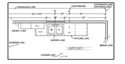
Lines on a drawing have their own special meaning and purpose. Standardized line types were developed for use in the industry. These line types are referred to as the Alphabet of Lines. Each line type should exhibit a certain thickness on a finished drawing, known as line weight. The thickness relates to the importance of the line on a drawing. The typical leads used are H, 2H, 4H (2 mm), and/or 0.03 mm, 0.05 mm, 0.07 mm, and 0.09 mm. Line weight on a drawing varies from a thin line to a thicker line. The line types typically used on NKBA drawings are illustrated in Figure 1.
Visible Object Lines
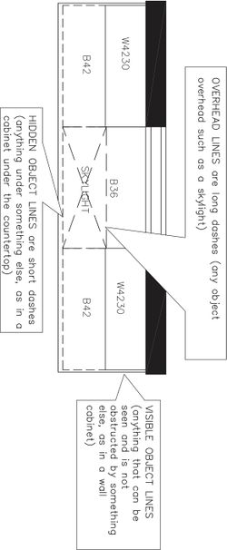
Visible object lines, shown on Figure 2, define the main outline of objects. On a floor plan, items include walls, cabinets, counter, flooring, furniture, some appliances, and any other item not covered or hidden in any way. The lines for visible objects will vary in weight and thickness in accordance with the object’s importance on a drawing. Walls typically are drawn as thicker visible object lines. Lines for cabinets, fixtures, and other items are drawn with a medium thin yet dark line. Wall lines are thicker than door lines. The door line isn’t lighter but may look lighter since it is a thinner line. No matter how thick or thin a line is, it needs to be dark enough to be visible when the drawing is reproduced.
Typically a 0.9 mm lead is used to produce the thick line, 0.5 mm lead is used for a medium line, and 0.3 mm lead is used for the thinnest line. For the standard 2 mm lead holder, the H lead produces a thicker line and 4H produces a thinner line. With the standard leads, the lead necessary to produce a particular line thickness will vary with the user, tooth of the vellum (roughness), and the pressure applied while drawing. Most draftspeople use a range from H to 4H. Many prefer to use a 2H for drafting the object lines with a 2 mm standard lead holder (see Figure 1).
Fixture Lines
Fixture line is a term often used for the lines that form the shapes of kitchen, laundry, and bathroom fixtures and appliances. A fixture line is thinner than a wall line, which allows the viewer to properly distinguish between items.
Hidden Object Lines (Hidden Lines)
Hidden object lines (hidden lines) show edges and surfaces that are not visible but are hidden below a visible surface. Lines for the base cabinets are drawn as hidden object lines since they are below the counter surface. We typically do not indicate the toekick or shelving, as doing so would make a drawing too busy. The hidden line for the base cabinets on a floor plan ends where the front of the wall cabinet line begins. Objects in an island, such as cabinets and appliances that are below the counter surface, must be indicated with a hidden object line as well. A half wall supporting a counter such as an eating bar would also need to be dashed as it is under the counter surface.
Hidden lines are drawn with short dashes 1/8″ (3 mm) long. The spacing between dashes is 1/32″ (1 mm). The adjoining hidden lines must touch each other at corners and also touch the solid line if it intersects. To ensure a clear definition of lines and corners, there should be no gaps. These lines should be a medium line weight.
Overhead Lines
Overhead lines represent objects above the floor plan cutting plane line at the ceiling plane. These include items such as skylights, soffits, extensive moldings, and the like. Overhead lines are thin, dark, long-dash lines (¼″ to ⅜″ in length) to make them distinguishable from the dashed line of base cabinets or pony wall, under a countertop.
Dimension Lines
Dimension lines are used to show all of the necessary dimensions and clearances on a drawing. Dimension lines run parallel to object lines and show distances with a size dimension. On an NKBA drawing, dimension lines have the numerical dimension in the line itself. All dimensions for NKBA drawings are indicated in inches (cm) and fractions of an inch (mm). The dimensions are placed in the line and are positioned so all can be read from the bottom of the drawing. This method is referred to as “read from the bottom”. Another acceptable method for dimensioning has the horizontal dimensions read from the bottom of plan and the vertical dimensions read from the right side of the plan. This method is referred to as “read from the right.” Both methods are used in the kitchen and bath industry. In AIA standard drawings, dimensions are placed above the line. Dimension lines on NKBA drawings are spaced at a minimum of 3/16″ (5 mm) apart, with ½″ (12 mm) spacing most commonly used. Chapter 5 discusses dimensioning techniques.
The dimension line itself is drawn as a thin dark line. It is thinner than the object lines so there is no confusion between the two. The dimension line ends at the intersection point of the extension line (witness line) by 1/8″ (3 mm). Leads used are the 2 mm, 2H, or 4H, 0.25 mm or 0.3/0.5 mm. Again, for NKBA standard drawings the dimension must be placed in the dimension line and for AIA standard drawings the dimension is placed above the dimension line (see Figure 1).
Extension Lines (Witness Lines)
Extension lines extend out from the visible object line of the walls or objects and are used to terminate the dimension lines. Extension lines are thin, solid dark lines. The extension line must not touch the wall or object and should have a 1/16″ (1.6 mm) to 1/8″ (3 mm) gap from wall or object line. In the industry, a 45-degree slash is used to terminate dimension lines. Dimension lines can extend 1/8″ (3 mm) past extension lines or end at extension lines. For horizontal dimensions, the slash goes from bottom left to upper right. For vertical dimensions, the slashes go from upper left to bottom right (see Figure 1).
Centerlines
The centerline is used when dimensioning to locate the centerpoints of appliances and fixtures on NKBA drawings. This helps ensure proper installation of plumbing and electrical items. The centerline is also used to place the centerpoints of new windows on the construction plan. Centerlines are drawn with alternating long and short dashes, with a symbol at the end, identifying it as a centerline.
Cutting Plane Lines
Cutting plane lines on a drawing show where a cut or slice has been made to create a section view. The cutting plane line is a thick, dark line with arrows on the ends to show the direction where the section was taken on the drawing. The line is either a series of dashes of equal length or a series of long and short dashes. If the symbol has two arrows, it refers to a section drawing. If it has only one arrow, it refers to a detail drawing.
Section Lines
Section lines on a drawing indicate a surface that has been cut or sliced in a section view. Section lines are thin lines drawn parallel to each other at a 45-degree angle and spaced evenly at 1/16″ (1.6 mm) apart to 1/8″ (3 mm) apart. Section lines are also referred to as hatching. A section view/drawing is often used to show the interior components of an item, such as a cabinet; it can also show how something is constructed.
Break Lines
Long break lines are most commonly used to indicate where a part of the drawing was removed or not drawn in its entirety. The break line is often used on a wall to indicate that the wall continues on. Break lines can be used for many different items on a floor plan, section, or other drawings. Short break lines have the same purpose as long break lines. They show where an item on a drawing would continue on (see Figure 1).
Leader Lines
Leader lines are very useful for placing text or a dimension in a limited space on a drawing and for adding specific notes pertaining to the drawing. The leader line can be a straight line or curved. There are several acceptable types of leader lines used on a drawing.
Leader lines typically have an arrow at one end and a note for the drawing at the other end. Several types of leader lines are acceptable. The leader is a thin dark line (see Figure 1).
Construction Lines/Layout Lines
Construction lines or layout lines are very light lines that are used to assist the draftsperson with drawing and placing object lines. These lines are drawn lightly and are easily erased if necessary.
Guidelines
Guidelines are light lines used for architectural lettering on a drawing. These lines are drawn lightly and are not meant to be erased. A lettering guide or Ames Lettering Guide is most often used to draw these guidelines. The guidelines will regulate the height of letters so that they are consistent on a drawing. Lettering on drawings will need to vary in height depending on its purpose, guidelines will assist in properly setting those heights.
Borderline
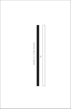
The borderline is the heaviest line found on a drawing. This is the line drawn around the perimeter of the vellum. It should be located ½″ in from the edge of the vellum. Title block vellums have the borderline preprinted. If you do not have preprinted vellum, you may draw the borderline and titleblock on every drawing sheet All drawings should have a borderline and titleblock. Figure 3 summarizes line types found on drawings.
Tips for a Professionally Drafted Drawing
Follow these tips for good drafting techniques that will result in professional-looking drawings.
- Close all gaps at corners. Drawing should have crisp corners.
- Erase any extra lines or double lines using an eraser shield.
- Rotate your lead holder slowly while drawing the line to achieve consistent line weight (thickness).
- Use appropriate line weights for line importance on a drawing.
- Lift the parallel bar when moving it so it does not smudge lines.
- Always use a drafting brush and never your hand to remove eraser crumbs.
- To prevent lines from smudging, place a piece of tracing paper over the completed part of drawing when drafting an adjacent area so your hand does not rest on the drawing itself.
Standard Symbols for Drawings
In the industry of design and architecture, standardized symbols are used to represent various elements found in drawings. These standardized symbols are understood by all trades and other individuals involved with the project. In the kitchen and bath industry, we use standardized symbols from the AIA on our floor plans and other related drawings.
Drawing standards are necessary for universal communication within the design industry. Each drawing in the set of NKBA plans has a great amount of important information needed for the design project. The symbols on a drawing represent elevation and section references, construction and building elements such as windows, doors, walls, appliances, fixtures, lighting, electrical components, flooring, and the like. Each different drawing within the set of plans has its own purpose and symbols to represent items specific to that drawing.
For example, the mechanical/electrical plan shows the mechanical and electrical components on that drawing. If these components were placed on the floor plan, it would be far too busy and could be confusing to interpret. On a construction plan, we show the symbols for walls to be removed, existing walls to remain, openings to be closed and new walls to be constructed. Construction plan symbols would be too much information to be used on a floor plan. There are symbols specifically used for floor plans, elevations, mechanical/electrical plans, construction plans, and other drawings.
Wall Symbols
Two techniques are used to draw the walls on an NKBA floor plan. The walls typically are just two thicker lines representing the sides of a wall and are not filled in, or they can be pochéd solid. The term poché (po-shay) means to draw a repetitive pattern to represent the material texture of a particular item. For example, when a wall is pochéd, it is drawn with the appropriate symbol such as a solid black wall. A pochéd wall can be filled in with lead or black ink. However, because filling in the opening by hand is very time-consuming, open walls are used most often.
In a plan, if there is a half-wall or wall that does not touch the ceiling, a note must be placed by the wall stating the height of that wall. If it is a half-wall under a surface, such as a counter, the wall would be drawn with a hidden line, with a note of the wall height.
Walls are drawn to scale, in the thickness that represents how they are constructed (i.e. wood stud walls with gypsum board cladding). Typical existing interior walls are 4½-inch (114mm) thick and exterior walls are 6-inch (152mm) thick.
The following walls symbols are typically used for construction plans. Construction plans show any changes made to the existing walls. Newly constructed walls should indicate the type of material used in construction (see Figures 4).
Door Symbols
Each door type has its own symbol that is standard in the industry. The floor plan symbols represent the type of door (i.e. pocket door, bi-fold door, swinging door, etc.) and how it opens into the given space. The door thickness, hinging (or swing), and casing should be indicated on the floor plan. The door is drawn to scale and is the same length as the opening. It is standard in the industry to draw the swing of the door on the floor plan with a 90-degree opening. The door may be drawn at a 45-degree opening if there is an adjacent door. Typically, when placing the door on a floor plan, it should open into the room and open against the wall or tall cabinet.
A door schedule is only required with new doors. The door schedule is a table that lists all specifics for doors in regard to size, quantity, hinging, manufacturer, and other important information. New doors are indicated by a letter in a circle placed inside each door opening on the floor plan and cross-referenced in the door schedule. If there is only one new door, the schedule information can be indicated directly on the floor plan in note form. Figures 13 show typical door symbols used on kitchen and bathroom drawings.
Window Symbols
Each type of window is represented by its own symbol. On a floor plan, the type of window must be indicated as well as the casing. Sills typically are not shown unless a particular interior treatment is to be used, or this information can be added in a note. An elevation shows how the window will look in two dimensions on the wall height above floor, wall space on left and right side.
For an operable window, it is optional to indicate the direction of the active panel. The active panel and direction of movement is indicated with a dashed line. Glass block is shown as a series of squares or rectangles with a listing in the specifications. Skylights are shown using long dashed overhead lines and are labeled inside the symbol. All pertinent information should be referenced at the side of the window or off to the side of the drawing, on a legend you create. Figure 14 shows typical window symbols you will find on a floor plan. Glass block is shown as well.
Stair and Ramp Symbols
Stair symbols represent the various types of stairs found in residential construction. A directional arrow placed on the stair symbol indicates the direction of the stairs. The direction either “UP” or “DOWN” is also written by the arrow. The direction would be from the given floor to the direction the stairs go. A break line often is used to indicate that the stairs continue to another floor. Most draftspeople draw all treads on the plan. Indicate the direction of the slope with an arrow leading from the main floor area to the secondary area and the word “UP” or label “DOWN” if the direction of stairs goes down from the referenced floor (see Figure 15).
Elevator Symbols
Elevators and hydraulic lifts are indicated with an “x” inside the outline of the item. The “x” is used to indicate that the unit runs through the entire space beyond the floor and/or ceiling. Include the appropriate door symbol to show the elevator opening (see Figure 16).
Kitchen Appliance and Kitchen Fixture Symbols
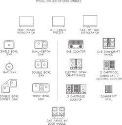
There are standardized symbols for kitchen appliances and fixtures. The floor plan symbols are drawn as representations of how the item looks in plan view. Some manufacturers have templates with appliances and fixtures on them. You also can duplicate images of the appliances by using shapes found on a geometric template. Figure 17 shows typical kitchen appliance symbols and fixtures found on the floor plan.
Appliances must be labeled on a drawing for identification. Typically, a circled number is placed on or by the appliance. This circled number is also placed in the specifications on the right side of the drawing with a description of the item. The number on the plan and information in the specifications must cross-reference one another. Some designers prefer to include a label with the name of appliance on the floor plan next to the item. Make sure there is enough room for the description so the drawing doesn’t become too cluttered. Chapter 5 presents additional information regarding the specifications.
Indicating the appliance door swings on the floor plan with a dashed line is optional. This technique shows the appliance door clearances within the space on the floor plan. The NKBA Kitchen & Bathroom Planning Guidelines show recommendations for appliance door clearances to create a functional workspace.
Bathroom Fixture Symbols
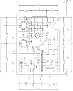
Bathroom spaces also have standardized symbols used for floor plans (see Figure 18). These include fixtures (i.e. lavatories, toilets, tubs and showers, fittings, grab bars, accessories, and more). The symbols are identified by a circled number and cross-referenced in the specifications on the right side of floor plan drawing or may be labeled on the floor plan if there is enough space for the lettering.
Flooring Symbols
Flooring symbols for the material used may be indicated on the floor plan. The acceptable technique is to draw a partial example of the flooring. Note that the entire space does not need to be drawn with the symbol. Rather, fade out the symbol at the edges, to end drawing the flooring symbol. Indicate the description in the specifications on the right side of drawing. If there is not enough room on the drawing to provide a good indication of the material to be used, it is best to leave the material symbol off of the drawing and to provide a separate drawing for flooring details including transitions to other types of flooring this will prevent any confusion.
Mechanical Symbols
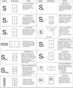
Kitchen and bathroom mechanical plans have specific standardized symbols used to indicate the lighting, electrical, plumbing, heating, and ventilation. It is very important to use these symbols accurately because professional tradespeople must be able to interpret your drawing and install items in exact specified locations. Every symbol on the floor plan must be cross-referenced with the symbols in the mechanical legend. Although the list of symbols is extensive, sometimes with ever-changing technology, a symbol does not exist for a new specified item and a new one will need to be created. Most symbols found in Figures 22 to 26 are consistent with the AIA’s Architectural Graphic Standards Manual. However, some symbols are unique to the NKBA to keep up with changes to the products that kitchen and bath designers must specify. Occasionally you may encounter a product and may not be sure of the correct symbol. If a resource fails to provide you with the correct symbol, you may need to create your own. When creating a symbol, you must describe it in the mechanical plan legend. Do not take this as permission to develop your own set of mechanical symbols.
Keep in mind that there are several acceptable industry symbols for some items. Company protocol may dictate which one to use. The following pages include mechanical symbols seen on most kitchen and bath drawings. Next to each symbol is a description and picture of the item.
Graphic Symbols
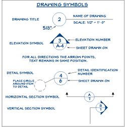
Symbols are placed on t=he floor plan to indicate that an elevation drawing and/or a section drawing is available (see Figure 28). These symbols link drawings together. The title symbol is used for the title of a drawing. This will indicate the number assigned to the drawing.
For the elevation symbol a circle with an arrow is used. The arrow points to the wall for which the elevation was drawn and where the viewer would look. The elevation is a two-dimensional drawing and shows exactly what is placed on that wall.
The detail symbol locates the area or component that is drawn to a larger scale to show how the item is constructed. The number of the drawing and the number of the sheet where the drawing can be found are placed in the circle.
For the section symbol, a circle is used with a long line that cuts through the area where the section is. The number above the line in the circle indicates the number of the drawing. The number below the line indicates the page it is found on. The section can be located on the floor plan or an elevation depending on where the cut was made. Note the symbol for a horizontal cut and a vertical cut.
Summary
Using standardized symbols for all drawings in a set of plans helps with communication among all trades, allied professionals, and clients. The AIA has standard symbols typically used in the industry. There are some variations of certain symbols that are also acceptable in the design industry. Line quality on a hand-drafted drawing is important. Line weight helps the viewer to better understand the details of the space. A hierarchy of lines exists, along with recommended line weights. The leads designers use can vary depending on which lead better meets their needs for producing the desired line thickness.
The types of lines are standardized and must be used in their proper locations on the drawings. The centerline is very important for kitchen and bath design. It denotes the center points of appliances and fixtures necessary for proper installation.

